|
Quick Change Toolpost |
|
|
|
 |
A quick change toolpost based
somewhat loosely on the design that Vikki built. I had already bought the
steel for the post, so I decided to make it out of steel rather than
aluminum. Not that it took any longer….
|
 |
Starting off with a 2.5 inch
square piece of 1018 steel, mainly because that’s most of what’s available.
I overdid the milling a bit, and finished all the surfaces. It’s about 1 1/2
inches thick. The next step is to decide on the location for the dovetail,
how many, and where to put the holes. |
 |
The location for the
dovetail was placed squarely in the middle of the length of the toolpost.
This slot is about 1/4 inch deep, which is all the dovetail that a 60 degree
dovetail cutter 1/2 inch in diameter will do.
You’ll notice , in the second picture, a bright slot where the dovetail
starts. I’ve decided to blacken the metal to be removed with a marker. This
allows me to see where I’ve yet to go. I was very conservative, and removed
only about 10 thousandths each pass. This took quite a while.
However, I decided that before I did all this, I would try out the
dovetail cutter, see how well things worked, and make some gauges in the
process.
|
 |
 |
Here’s the edge marked on the
gauge. The countersunk hole is because I’m cheap enough to use aluminum over
again, and it won’t matter that the hole is there. You can see I’ve got just
a little more to do for this dovetail on this side. |
 |
Here’s the two gauges. They fit
well enough that they are a snug fit when you try to pull them apart.
There’s enough friction that it is difficult to move them up and down when
trying to pull them apart.
|
 |
The two gauges trimmed so that
they look like they’ve been made for each other. I meant to do that….
|
|
|
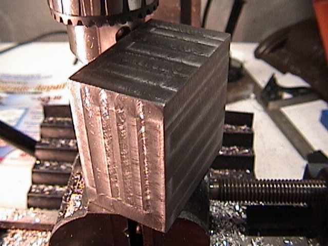
The toolpost with the dovetail
almost milled. You can see how easy it is to see the part that has yet to be
milled. Once I get close, I start trying with the gauges, and I also look at
the width of the slot. Note also that the dovetail cutter is milling out the
flat surface, and doing a nice job of it. |
 |
Last pass. The gauge fit and the
dovetails are done for the toolpost holder. |
 |
I tried to find a good way to
hold down the tool carriers, and finally settled on drilling a 3/8 inch hole
through the 7 inch long steel bar. Using the jacobs chuck made the setup too
flimsy, but when I tried to use the collets, the tool wouldn’t reach far
enough down.
|
 |
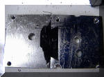
Time to stop everything, replace
a gear that had been mistreated, and do the torsion arm mod. You can see the
old hole below the attach point of the arm. The spacing is about 1 inch. I’d
rather have done it about 1/4 inch further up, but the results (in the
second picture) were good enough. |
 |
You’ll notice that there’s
enough travel so I can use the collet. It was worth the effort to move the
torsion arm. |
 |
This is the last bit of the
dovetail. I got rather tired of it, and started using an electric drill set
to very slow to turn the feedscrew.
|
 |
The tool carriers are finally
milled. Now to keep doing stuff that won’t ruin the effort. There was enough
space to make 4 carriers out of this, and throw away the two sections with
the holes.
However, I decided to try to make something out of the other sections,
and looked at my knurling tool.
But first, some pictures of how I decided the whole thing would fit.
|
 |
As it turns out, I had to use
the chuck for the dovetail cutter. Not happy, but it worked. The nice blue
block is the toolpost sitting on one end. |
 |
And the toolpost is sitting on
the other end, so unless I’ve managed to make it odd shaped, it all works. |
 |
I’ve cut the pieces to size, and
realized that these pieces are awfully thick. I could have gotten a piece of
steel a little less thick. Still, it turned out well. I could cut all these
on the metal saw.
|
 |
Before I did that, though, I
tried to see how this would fit. The toolpost hangs out over the left edge
of the compound by 1/2 inch, and goes in by the same amount. I could trim
off that inner 1/2 inch, but the one to the left with the tool carrier has
to stay. |
 |
As you can see, cutting the half
inch off the tool carriers could have been a real problem, but I had
something that would fit in the metal saw’s vise, and would also hold the
tool carriers securely. There was enough pressure to lock the carrier in
place. |
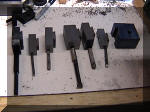 |
All the carriers cut to size.
Boring bar to left, 1/4, 5/16 lathe tools, circular boring bar, two more
lathe tools, 5/16 and 3/8. The toolpost is to the right. |
| The handle and threaded rod are from the original toolpost,
and the small washer next to the handle keeps the handle at the proper angle
when locked. The handle above the cam goes on the cam, and the cam plate,
locking screw and washer are above the tool post.
|
 |
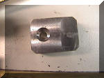
This shows the tool post block
with the hole for the cam and cam plate. The cam goes in the front of the
toolpost. The hole was drilled first, and the cutout for the plate was made
second. |
 |
The cam installed in the
toolpost. There’s a small flat milled on one side so the plate will lock
into place, although that doesn’t always happen. The hole below the cam is
for the locking screw, more on that later. |
 |
Here’s the cam. You can see that
the cam area is wider than the hole for the plate. There’s a small flat
milled on the cam for the handle, which keeps the handle from slipping. The
end is slightly pointed, which probably wasn’t needed, but looks nice. |
 |
The cam plate itself is beveled
on each corner so I didn’t have to make an absolutely square hole for the
plate. While it may be hard to see, there’s a little protrusion on the
bottom of the plate. It’s small enough to fit into the hole that the cam
fits into. This small part rides on the cam. |
 |
This last photo just shows the
position of the cam in relation to the tool post. The darker area on the
plate is the area the cam rides on. |
 |
This gives the best picture of
the cam plate with the cam installed. |
 |
Here’s the face view of the cam
plate. The screw is a 10-32 socket head screw. One of these days I’ll get a
set of counter bores for this, for now, it’s just a drill. The screw holds
the plate in place, but is left loose enough that the plate can move. |
 |
Here’s the handle for the cam.
The handle itself is made from a 5/16 inch bolt with the head removed. No
sense in making what you can buy for cheap. |
 |
Here’s the boring bar holder
(the square one) as finished, but without clamping screws. There’s about
1/16 inch clearance top and the tool is also inset by the same amount. |
 |
I bought a knurling tool, only
to find out that it would not fit the lathe. Not happy, I was…. You can see
the reason, the arm is far too long, even on the new toolpost. However,
suppose I didn’t need the arm? I had a carrier that had a hole already in
it. Just needed to thread that thing…. |
 |
The hole was too big to thread.
So I milled a small slot in the dovetail, and turned a nut down to fit into
a larger hole that had been counterbored. This is the carrier before it has
been cleaned up. |
 |
The knurling tool, an added
nylon washer, the carrier, and the nut. You can see how it was turned down
to fit in the hole. The top part keeps the nut from falling through and also
locks it into place. If it ever breaks, it’s easy to replace. |
 |
Very cleaned up, you can see the
slot for the nut in the back. There’s still plenty of surface for the cam
plate to push against. The carrier has been finished on a belt sander, and
the edges have been rounded a bit. The whole assembly will be blued, but
later. |
 |
Top view of the carrier. Plenty
of surface left on the dovetail. |
 |
This shows the position of the
knurling tool. It fits quite nicely, and just happens to fit the way it
should. There’s no height adjustment because the height adjustment is just
an eyeball measure, anyway. |
 |
The knurling tool in action on a
scrap of aluminum. |
 |
Here’s the top view. Everything
lines up quite well, and I am surprised, but happily so. There’s enough
adjustment in the cross slide to accommodate all different sizes of work. |
 |
Here’s one of the toolposts,
finished, blued, and with the height adjustment in place. None of these are
exactly the same height, but it really doesn’t matter.
|
 |
Here’s the second. I made one
that was for 5/16 inch tools, one for 3/8 inch tools. |
 |
Here’s the one that I left the
original thickness, so something good came of that. This takes 1/2 inch
boring bars, and the slot was made with a slitting saw, just a little at a
time. |
 |
Another view of the knurling
tool, blued and ready for use. |
 |
In case the idea of the height
adjustment never quite struck home, here it is in operation. The screw is
another 1/4 by 20 bolt, the capscrews are all metric so they fit what’s on
the lathe, and the knob is knurled with the tool above. |
 |
Here’s the toolpost, blued and
in place. The plate was aluminum, so that didn’t blue. This shows the plate
fully extended with the handle in the locked position. Everything turned out
rather well. |
|
|
Here’s the entire ensemble. The
various toolholders are shown together with the toolpost. I don’t think I
have enough toolholders, but that will wait until I get the energy to go
ahead and make another somewhat long project out of the tool holders. I’ve
got enough for now, and the toolpost itself is removable rather easily. |
| If I
were to do this whole project over again, I might make the toolpost a bit
smaller towards the center of the lathe. It has cost me a little cross slide
travel, but not much, only half an inch.
The cam mechanism seems to be a bit more complicated than it needs to be,
but I’m still working towards elegant simplicity. It’s a goal….
Bluing worked reasonably well, but I’d rather have had true blue rather
than black. I do think that two treatments was probably needed, but I’ll see
how this wears and reblue as needed.
I drilled one of the setscrew holes before I bored the hole for the knob,
and found that the drill ran off center by a lot. Strange that it did, so I
left that ‘till last, and it worked much better.
We’ll see how this works in practice, but considering the mass of steel,
it should be just fine.
|