|
Gearbox |
|
|
| A few
observations on how, and how not to make a worm gear drive for a telescope.
Since the major item is making the box, with the application elsewhere, this
is in the metalworking section.
|
 |
Nothing ventured, nothing
gained, so I decided to take the gear hobbing setup one step higher. I
decided to make a gearbox. Now I had a piece of 2 inch wide 1/4 thick
aluminum bar, and cut that in half. I shouldn’t have done that, in a sense,
because it led me to a number of interesting mistakes, and a few other
lessons learned. |
 |
The first picture was as
originally designed, the second picture is the one that works. |
 |
Firstly, a picture of the
hobbing setup done as a test. This does work, and did produce a gear. So I
took another chunk of aluminum, and used an existing 1/4 inch hole, and made
a gear hobbing setup that was a bit more elegant, well, perhaps I thought
so. I’m going to do something about that a bit later, say, put in some ball
bearings. I’ll need them. |
 |
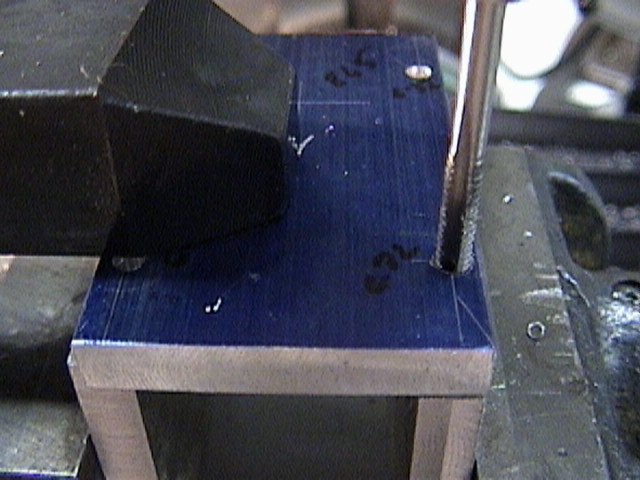
Now the second picture is of a
new gear blank (the first one was just a section of bar stock. This new gear
has a hub turned down for a setscrew, which is a bit easier than a keyway.
The picture shows the gashes made by the 1/4 –20 tap as it cuts the first
threads in the gear blank. I wanted this to work, because cutting the gear
blank wasn’t really easy. I was trying to be cheap with the metal and used
too little. I should have used a longer chunk. |
 |
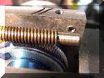
Here’s the gear after one
complete revolution. I hadn’t measured, and just trusted that the teeth
would come out right. Other than a small blurble, they actually did. That
was just lucky. |
 |
Now other than not measuring, I
hadn’t made any serious mistakes yet, at least, none that I know of now.
This shows the gear a bit further down the road. I use tapfree fluid to
smooth the cutting. It really doesn’t dissolve the blue layout dye. |

 |
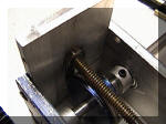
A different view of the setup.
The large chunk of aluminum bar on the left is a collar to keep the shaft in
place. Not very elegant, but it did work. I will replace this with a more
elegant setup, and use some ball bearings to let the gear turn well. I’ll
also widen the setup to accommodate larger gears. I may turn some that are
up to 3 inches in diameter. The last picture shows the gear as produced,
which isn’t too bad. I kept this going at low speed, and that kept the
positions relatively constant, not too much knock and stress, although cuts
should be light, only a few thousanths or so. Fortunately, the mill does all
the work, so it’s only time.
|
 |
Now here’s the two plates of
aluminum. They’re bolted together so the holes match, and one hole was
already there, in one plate. So I ignored it (not a mistake). You can’t see
the problem yet. |
 |
The gear is positioned to allow
enough spacing for the worm. If things look a bit crowded, they are.
However, it all fits so far. |
 |
Here’s how the worm is planned
to fit. Notice that it nicely clears the bolt holes that tie the plates
together. I have another idea in mind for the plates, though. (and that idea
had its own problems, see later). There’s an equally small amount of
clearance on each side of the worm gear. |
 |
What I did here was to space the
two sides apart, and clamp the motor mount plate on top. This is a
commercial clamping setup, and this is the reason we buy this kind of thing.
It was extremely easy, and held well enough to drill the matching holes.
|
 |
Tapping the holes. It’s easiest
to tap straight through. I’ll drill out the top holes and countersink them a
bit later, although I could have done it in one series of operations without
moving the plate. Notice that the motor plate sits on top of the sides,
relatively speaking. You might start to see the problem. I didn’t. |
 |
The worm screw would go across
the far side, down at the bottom. You can see the bottom support, which is
cut out of a piece of bar. Now this I did reasonably well. Without moving
the drill bit, having drilled the hole to match where the worm would go (I
took a piece of rod, pointed the tip, put it in the mill chuck, and ran it
down vertically. Where it stopped was where to drill for the worm gear. The
gear is pushed to one side. |
 |
A picture of the motor plate
with the pilot hole drilled, (more later) and the worm end support mounted. |
 |
What I did, without moving the
first setup, was to put the motor mounting plate on. The drill was set up to
drill that support, so the hole drilled for the motor should align with the
one for the support. This turned out to be about a #10 drill, because of the
way I turned the worm down. |
 |
Drilling the motor hole. It’ll
have to be reamed out a bit, but this isn’t bad. Go buy the silver and
deming drill sets, 1/2 inch shank and will drill up to an inch hole. Works
in aluminum without a problem. Saved me lots of problems. Produces lots of
swarf. See the problem yet? Neither did I. |
 |
Here’s the motor plate mounted,
it sticks up a bit, but that’s as designed. You can see the worm gear and
the worm support in the back.
|
 |
I turned down the end of the
brass rod to make a fit into the hole. I’d really like a ball bearing for
the shaft, but that may not be. The shaft extends out the motor hole,
waiting to be trimmed to length. |
 |
Here’s the end of the worm shaft
turned down. It matches the size of the shaft on the stepper motor, so one
drill through will get both of them. There’s a bit of a problem here, but
not the main one. |
|
|
Here’s the motor mounted. The
problem still might not be obvious to first view, but it is there.
The motor has screws that run through almost all the way and are tapped
in the near motor frame. They mount the motor with screws that come in from
the bottom into threaded holes.
|
|
However, the motor is so wide that the mounting holes line up very well with
the sides of the gearbox. In fact, the motor covers two of the attachment
holes for the motor plate, and the sides cover all but two of the motor
holes. I can’t win with this one. So what I think I will do is to redo all
the metalwork, put in the bearings I want, and other good stuff. It’s a nice
proof of concept, but it isn’t sturdy, not at all. Also look at the shaft
coupler. It’s really close to the worm gear itself, so close that I had to
turn it back to get it to fit. I think I’ll try to make this a bit longer so
I have more room between the worm gear coupler and the gear itself. I also
want those ball bearings, and I might just put one on the stepper motor
worm, too. |
| So here
are the solutions: mount the motor plate between the sides, not on top of them. This way,
all I have to worry about is the holes running into each other.
Make the sides longer. I’ll have to, anyway, because the motor plate
takes up 1/4 inch more this way.
Ball bearings for the driven gear. The shaft will come out 1/2 inch on
the non telescope side, and I’ll put some sort of indicator plate there
for rotation. The driven shaft will come out about 2 inches or so. It will
drive the telescope through a rubber wheel. I’ll need another ball bearing
support at the end because all the weight will be on that one shaft. (or
at least 1/3 of the telescope).
The interior plate will be thinner, and will probably have a small ball
bearing on it. I’ll extend that about 1/2 an inch beyond the gearbox
walls, because that will be an attachment point where I’ll put another
indicator wheel. That’ll show that the stepper is being driven and is
moving.
I’ll also allow some space for the angle bracket mounts. I’ll need two
of them to attach to the telescope base.
Moving the sides a bit further out gives me more room for the setscrews
on the shaft coupler.
I’ll probably think of more stuff later.
|
| And
here’s what I tried: 1) Mount the motor plate between the sides, not on
top of them. This way, all I have to worry about is the holes running into
each other.
This is a good idea, but it had a problem, too. That extra distance had
to come from somewhere.
The gear was so close to the sides that they had to be milled down a bit
for more room
2) Make the sides longer. I’ll have to, anyway, because the motor plate
takes up 1/4 inch more this way.
Now that worked, but I only made the sides a bit wider, they needed to be
more than 1/2 inch because I lost the full half inch in getting the motor
plates mounted.
3) Ball bearings for the driven gear. The shaft will come out 1/2 inch on
the non telescope side, and I’ll put some sort of indicator plate there for
rotation. The driven shaft will come out about 2 inches or so. It will drive
the telescope through a rubber wheel. I’ll need another ball bearing support
at the end because all the weight will be on that one shaft. (or at least
1/3 of the telescope).
So far: this has worked.
|
| 4) The
interior plate will be thinner, and will probably have a small ball bearing
on it. I’ll extend that about 1/2 an inch beyond the gearbox walls, because
that will be an attachment point where I’ll put another indicator wheel.
That’ll show that the stepper is being driven and is moving. So far, so
good. I don’t have a drill the exact size I needed to make the ball bearing
fit properly, but I got close.
5) I’ll also allow some space for the angle bracket mounts. I’ll need two
of them to attach to the telescope base.
Haven’t put them on, yet, but there’s holes already drilled for this.
6) Moving the sides a bit further out gives me more room for the
setscrews on the shaft coupler.
And that was needed
7) I’ll probably think of more stuff later.
Still thinking about that one.
|
|
|
Now as I originally redesigned
this, the long horizontal sides were vertical. Since they have 22 mm holes
bored in them (limit of the 4 jaw chuck!) they were good to preserve. The
problem was that the worm screw was so short that I couldn’t attach it to
the stepper shaft. This was not a Good ThingÔ
I had to turn the sides by 90 degrees, which happily made everything work. |
 |
You can see the driven gear
bearings and the driven shaft. The shaft is 5/16 stainless, which is
almost a proper fit for the 8 mm inside bearing races. Good enough, I
suppose, for the experiment. |
 |
Inside view. The two shaft
collars hold the shaft in place, they’re homemade. The gear is in place, and
the bearing for the end shaft of the worm is more or less in place. I really
want the boring head, I do. Still on backorder. I need a way to make precise
holes in flat plate without the lathe. |
 |
Top view. Everything more or
less lines up. |
 |
Now this is the shaft coupler
from the first attempt. Notice that the holes for the motor mount are a bit
egg shaped. This allows me to adjust for “manufacturing tolerances” and
adjust the motor position so the worm fits the gear a bit better. The
mounting holes are counterbored a bit, because the screws are short.
|
 |
Another view of the motor holes.
I’ve got to figure out a better way to align motor holes and align large
holes. This works, but I’m not happy with fit and finish, here. |
|
Evaluation: Well, there are bearings were there needs to be bearings, and
that’s good. The fit and finish and spacing issues were interesting, and
luck played a good part of some of it.
I think this design is better, and it allows more space for the worm
screw, which is needed. I’m happier with ball bearing assemblies installed,
although I’m going to put in a precision sleeve for the gear, since I messed
it up a bit. I’m waiting for a precision ream to come in, just don’t have
the right size. I’ll leave the top open, and the next part will be to put
angle brackets on the sides to allow mounting to the base.
Electronically, I need a stepper motor tester, and that’ll be the next
thing. That will be a simple electronics project, and I’ll just use the
lathe and mill for construction as needed. No complicated mechanicals here.
I’ll post details after it’s built, but it will probably use a one chip
microprocessor to accommodate various types of stepper, various pulse rates,
and other good things. I guess I’ll build it as a general purpose piece of
test equipment, and we’ll see what happens.
So far, the mechanical assembly is ok, but I’m realizing that I rather
hate building gearboxes, at least, the ones that go badly.
Still, though, managed to salvage stuff, so this is good.
|