|
MIcroMill CNC: Z Axis |
|
|
|
A project in process
(aren't they all?) |
|
Since I don't need another project, I decided to immediately
start one. I wanted (and actually will have a use for) the MIcromill
when it's CNC'd. So what I decided to do was read that entire part of
the Yahoo Micromill CNC archives that I had, I got a part
number of the gas strut, and a part number for the bearing assemblies.
Time to do it all. I also ordered the bearing blocks for the X and Y
axis so I could replace them when I modified them. |
|
This is part one of a 3 or so part series, covering the Z
axis, then X and Y. It will be posted in pieces as I start to work on
it. |
 |
The
first thing I needed to do was to install the gas strut for the Z axis.
The part was gotten from Mc-Master Carr and is a 25 pound thrust extension
with xxxx travel and an M8 thread on each end. Time to make your own
mount here. I was rather surprised at the size of the strut, but as it
turns out, it's the extension that determines the size. Next, it's up
to me to make sense of it. |
 |
First,
I find out that the base is not square to the bottom of the column.
That makes it imperative that I mount the base of the spring differently.
I can't use the little red base. |
 |
This
gives you an idea of how high that base will need to be, and how long the
strut is, in relationship to the whole micromill. The strut is at full
extension. |
 |
I will
mount the bottom of the strut on a simple aluminum plate, 1/4 inch thick.
I've drilled holes and will mount the plate under the column bolts. |
 |
The
plate as mounted. I decided to mount the strut so that the base is out
a bit, and clears the column by a bit. |
 |
I've
actually mounted the strut on the plate here. Closeup is next.
|
 |
The
placement is rather arbitrary, but seems to work so far. I could have
picked the back, but the spring would have gotten in the way of the screw.
Mounting it on the front would have put it in the way of the work, and on
the left side would have put it in the way of the gib adjustments. |
 |
I
decided to use a piece of thick angle bracket. There are several
reasons. One is that I had it. Second is that the additional
metal will give me strength in two dimensions, both at right angles.
The third is that it was just long enough as is. Mounting both the
spring and the plate, I have the headstock Z axis clamp removed and I will
be mounting the support angle on the side. I'll be using a 1/4-20
thread cap head screw. No countersinking needed and the allen heads
are hard to strip. |
 |
This
is how to tap. You use a tapping adaptor which is spring loaded, which
fits in the end of the hand tap. If you don't move the table in X or
Y, you're automatically aligned. Very worth while addition. |
 |
Details of the bottom of the strut support. You can't remove the angle
with the strut attached, but that's not a big deal. I had designs on
that aluminum column for motor mounts, but I think I won't go there. |
 |
I've
put a scrap piece of 1/2 inch aluminum at the top of the column. With
maximum extension, it's about 3/8 of an inch inside the maximum extension of
the spring, so that the spring will never hit the stop. I will be
doing metal finishing later. This is just for fit, not finish. |
 |
The
side view. The screws are 10-32 because I had them. They're
about 1 inch long or so, and the strut is tapped between them. I could
put one on the 90 degree part, but decided against it for the moment.
Be sure to round the inside corner, since the inside corner in aluminum
extrusion is rounded, not square. |
 |
The
column partway down. If you do this and want manual operation, pick
another way, since the hand wheel will get in the way of the angle.
It'll also be awkward to use. |
 |
This
is the lowest extension of the head, which is not bad. However, if you
get the chance, you might want to mount the block differently. This is not absolutely the best way to mount that spring, but it will work.
The bottom of the Z axis screw has a washer that rubs against the
bearing block, the top has another washer. Lots of friction.
|
 |
This
is the lowest extent of the head. That's about a 1 inch parallel for
an example. This low extent is fine. The quill can always be
lowered if needed. The maximum extent is the original extent of the
head, so no big problem there.
I had thought that the gas spring was way too big, but in
fact, it was not.
|
 |
Top
view at the top extension. The head will not go up any further.
You can see the clearance between the strut and the head.
I decided to try to build another Z bearing block. I
was going to use the standard skateboard bearings. Those were cheap,
so all I'd be out would be a small piece of aluminum. |
 |
First
thing is that the old bearing block is used as a pattern. A transfer
punch is used to match the screw location. It is not symmetrical in
the piece of aluminum I used. I'm using the tap guide as a spud. |
 |
I
drilled a 1/2 inch hole completely though. This clears the center
raceway of the bearing.
I first made cuts and then did not quite realize that I
was going to cut into the vise to make the hole for the bearing.
Either use a larger piece of aluminum (.75 is not enough) or use two pieces
of sacrificial plate to start with.
I bored this about 1.25 inches deep. It really had
to be that deep. |
 |
This
is the boring head tool set for the right size. You sneak up on it
with about 0.040 or so cuts.
|
 |
This is
the first part done. There are several things here. One is that
the bearings extend into the column. The second is that I did not properly align the top
bearing and bottom bearing, so that the shaft, which is about 8mm, did not
fit properly. I ended up turning down the shaft, which was not needed,
and should not really be done. I did wobble the top hole, which allows
the bearing to move a little. Next time, I will be more careful.
The screw length requires that the two bearings be this
close. I want to use the existing screw thread to preload the
bearings. |
 |
Roughly, this is where you want it. The bottom of the bearing is
exactly where the old bearing block was. The right most hole is easy,
since there's a lot of space there. The left most hole is tricky,
since it has to clear all the bearings and not hit the side of the column. |
 |
This
is the bearing block before holes were drilled to mount it. |
 |
A side
view. The thing that irritates me is that the bearings are a very nice
fit, with very little slop. Too bad that one of them is wrong. |
 |
You
can see that I turned down the shaft a bit. Don't do this, wobble the
hole or remake the bearing block if you must. The existing washer is
left on the screw. Behind the screw is the U shaped
slot that i cut to clear the bearings. I used a flat mill, then use a
ball mill to complete the job. I ended up wobbling it a bit, making
parallel passes down the slot. The middle was made a tiny bit deeper.
Note also that the right most hole is new, and the left
most hole is almost in the existing hole. If I have to, I can always
bore it out and put a nut in place to hold the old bearing block. |
 |
A good
view of the need for the bearing slot. |
 |
A back
view You can see how the mounting hole on the left is between the
bearings, and just about as far left as you can get. Any further left
and you are in the column wall. |
 |
Bottom
view, bored, you can see how the hole just misses the outer diameter of the
bearing. |
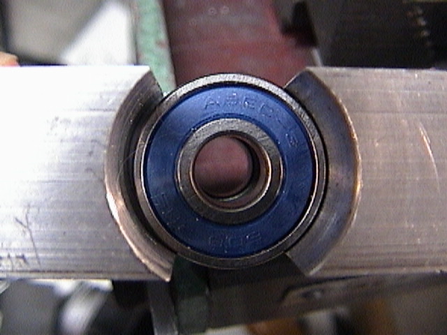 |
The
top bearing assembly, with the hole widened a bit. The bottom is the
only part maintaining radial alignment, and the top is acting as a thrust
bearing only. |
 |
I put
three bearings in to even out the spacing. A washer and knob nut is
sufficient. This ought to align the bearing axis to the shaft.
The right most screw is loose, and the left most is not drilled and
tapped yet. Use a transfer punch. You might be able to see an
alignment line that marks the edge of the bearings to the edge of the screw
hole. |
 |
Removing the extra bearings gives a better idea of what's up. Note
that I have bought a new screw to replace the one that I messed up. |
 |
Now to
make the adaptor. I decided to use a belt drive, since I had one (all
electronics). The adaptor will screw down on the existing shaft,
preloading the bearings. The thread is 6 mm 1.0. I want the bore
to clear the shaft, and the top of the adaptor has to be machined to match
the existing plastic pulley. This is the plan I
worked to. |
 |
I have
the thing internally threaded, the top cut to length, and I've left the 3/4
inch rod at the normal thickness, but taken off the surface oxide layer.
I've made all the left hand direction cuts, and will change lathe tools to
even up the shoulder. I need to remove the metal up to the right hand
edge of the middle oxide layer. |
 |
Cut,
more or less polished, and ready to cut off. |
 |
Cut
off with the bandsaw, I will turn the little piece off. |
 |
I've
already threaded the middle for a 1/4-20 screw. That will hold the
pulley on with a washer. However, the gear has a D slot with a keyway.
It's molded plastic, and does not have enough to profitably make a setscrew.
However, I can make this a splined shaft. |
 |
A
milled slot will cut half of the keyway. |
 |
Duplicating the same cut on the other side of the keyway gives me the
D/keyway combination. It turned out to be a trifle too large, so I put
it back on the lathe and just turned down a thousandth or so. Once it
fit, there it was. |
 |
The
pulley as a side view. This is an XL style pulley that I bought as a
set from All Electronics. |
 |
The
adaptor will screw down onto the shaft and bearings, preloading them.
You then tighten the setscrew and that keeps the adaptor locked to the
shaft. Tapped the same way as before. |
 |
This
is the Z axis bearing assembly without the pulley. Note that the
bearing block is firmly bolted to the column, and extends beyond the column
itself. I might trim it to the right. |
 |
Pulley
mounted on the top. The screw heads will get in the way, so I have to
countersink one of them a bit, or get a smaller screw head, perhaps pan head
or flathead if needed. |
 |
I know
that I will have to have a flat on the stepper motor shaft. You do
this because the setscrew raises a small ridge on the shaft. If you
make the shaft a pretty much exact fit, then the adaptor will jam on the
shaft. Putting the flat on the shaft moves the dimple out of the way
and the adaptor does not freeze on the shaft. A single pass with an
end mill is enough. The depth is about 0.020 at the max. |
 |
I've
turned the adaptor from 0.75 aluminum. I bored through by 8mm, which
is the diameter of the shaft on the pulley above. I cut the shaft
short, and removed the bearing. Then I reamed out the adaptor to
accommodate the stepper shaft. The pulley shaft is
straight knurled, so it was either bore out the pulley, or turn down the
stepper shaft, or knurl the shaft, or try to make the pulley a setscrew.
I could also have made an adaptor that cut out the center and just had a
bore in it. Things you think of after the fact. |
 |
Because of the various shaft lengths, this is where the motor goes. I
could have bolted the bottom of the motor to the bearing bracket, but that
seemed inelegant somehow. Again, adaptors and a bit of different
thinking could have resulted in a design that is lower to the motor and the
bearings. |
 |
I
bored out the motor mounting holes to 1/4 inch for this. Since the
machined part of the motor plate is the part that is perpendicular to the
shaft, that is the important part. |
 |
A
piece of angle bracket on the side is sufficient to mount the motor. I
put in a few washers to space the bracket from the motor end. I also
had to notch the bracket to clear the adaptor. You'll see that later. |
 |
Right
now, a single screw is holding this in place. In case you wondered, I
had to countersink the one cap head screw that this bracket is covering up.
|
 |
I'm
testing stuff here. The bracket is a bit tilted, and that means that I
will (of course) need that extra screw to mount the bracket properly.
The little blue box is the stepper motor tester. Since
it's unipolar only, and the motor is a 6 lead motor, I can use it to test
this out. Since a bipolar driver will be better, not at low end
torque, but at higher speeds, I can see how the design works. As is,
the tester does 1 and 10 steps/second. The power supply is giving me
12 volts for the tester, and the stepper is being run at 4.6 volts or so and
1.55 amps (if the meter manages to follow it) for two coils.
The motor is a bit under driven, but is a good test.
|
 |
Here's
the second screw holding the bracket in place. You can see the notch
for the adaptor as well. |
 |
Looking at the side, you can see the washers, notch for the shaft, shaft
flattening, and details of all the brackets. |
 |
As
mounted, and pretty much as done, but without the connectors and the home
and limit sensors. They're next. |
 |
First,
the system is running at 171 halfsteps/second. The ratio of the belt
drive is 25:41 (reduction). The leadscrew is 20 TPI, and the stepper
is 200 steps/rev.
So we're getting 170/200 rev/sec which is .855 RPS
which is 51.3 RPM (way slow), and that's 31.3 RPM delivered to the shaft.
That works out to 1.56 IPM.
So that means that I'll have to get up to about 1700 PPS
drive half step to get about 15 IPM, which is not too bad.
|
 |
I took
a 1 inch by 1/4 inch bar and mounted it parallel to the column. It
will be spaced out with small spacers from the column. More on that in
a bit. |
 |
A
little down the path. The bar has the three sensors mounted on it.
The upper one is the limit switch, the bottom one here is the home switch.
You can see that they are slightly adjustable.
The 4-40 tap broke in the headstock mounting block.
I thought that was really special.
So I moved the brass bar over a bit, and tapped for 6-32.
The sensors are not wired yet. |
 |
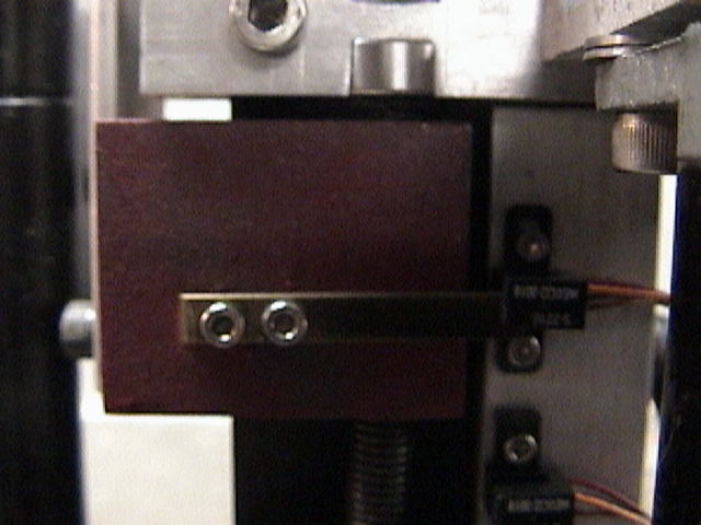
A side
view of the senor and the interrupter. The left/right (towards the
column, away from the column) can be controlled by adjusting the number and
thickness of the spacers. The entire bar can be removed with two
screws. This was one of the better ideas. |
 |
The
head at approximately the upper limit (actually, about zero on the up/down
scale.
I actually expect it to trigger a bit lower than this. |
| |
|
| |
|
| |
|
| |
|
|
Analysis: So far, it works, without
much of a problem. I will have to see how it works with better (or
different) drivers.
Things not to do:
1) do not machine the shaft at all. I think I will
eventually replace that shaft. I may or may not remake the bearing
block, but it doesn't really need to be replaced now. Main problem is
that the pulley assembly and the shaft will wobble. I may have bent
the shaft a bit when I was working with it, or it may have just have been
bent naturally. I also had a loose fit on the top bearing, and that
was within the bearing assembly itself, shaft to bearing hub. This
allowed slop.
2) It's possible to move the strut mounting up a bit, that
will work. Another option is to move it down a trifle. The main
problem is that one of the screws is in the way of either the Z axis handle
or the drive.
3) Probably better to make the belt drive lower and closer
to the motor body and to the bearing block.
Plusses:
1) I like the way the sensors are mounted.
2) the belt drive (All Electronics part number CGB-33).
The gears need to be mounted differently, but are useful as is. The
adaptors are relatively simple lathe work. The ratio is 41 teeth on
the large gear, and 25 teeth on the smaller one.
3) I had enough sensors for the entire mill (I think).
All Electronics does not have any more of them. They can be replaced
by something generic.
|
|
AFTERWORD: I did a few more things to
clean up the implementation, but not the design. The first thing I did
was to order another z axis screw from Little Machine Shop. Since this
did not have the unthreaded part narrowed down, it would fit the bearings
much better. However, I found at least one thing that had to be
done. Because the shaft had been cut down in the original design, the
upper bearing was off center, and could be assembled that way. This
was not a Good Thing ™.
I have a centering indicator, so I put the bearing block
back in the vise. I added the little side plates as best as I could,
and then left the bottom bearing in. I indicated from that
bottom bearing's inner race the diameter. That centered the shaft to
the bottom bearing, the inside of which had to clear the 1/2 inch hole that
I had bored. This way, the concentricity of the half inch hole didn't
matter as long as it cleared the shaft. With the boring head set to
the proper outer diameter for the bearing, I was able to make a pass down
the block, and clean up the hole. It was probably about .010 or so
off.
An 8 mm rod would run down the two bearings without a
problem, so the two bearings were concentric.
I found that the washers that I had used were suitable for
1/4 inch stuff, not 8 mm stuff (the shaft diameter). Adding a few 8 mm
ID washers made up for the (slight, if at all) manufacturing tolerance, and
the small amount that I had probably removed from the inner thickness of the
bearing block. Note to self: put locktite on the outer race of the
bearing to help hold it in, but probably not needed.
With this addition, the bearing block was reattached, and
the very slightly modified leadscrew was put in. You'd think I hadn't
learned anything, but I did modify the leadscrew a bit. What I did was
to drill and tap the end for a 1/4 - 20 thread, and put in a cap head screw.
Since the screw head diameter was bigger than the thread itself, I turned it
down. This is to give me a way of grabbing onto the end of the screw
without messing up the threads. Locktite can be used if needed.
When you assemble the top part, it screws down on the bearings and preloads
them. How well that will work is another matter. However, they
are cheap bearings. If I absolutely have to, I can put in
thrust bearings and either remake the block or just add spacers as needed.
Overall impression is that there's much less wobble, and
the screw did not move from side to side. It seems to be easier (by
hand feel, nothing else) to turn the Z axis screw.
Overall last comment so far: Do Not Turn Down The
Lead Screw. Second comment, you really have to watch the concentricity
in the two bearings. I'll remember that on the X and Y axis.
On to the X and Y axis. |