|
Mini-Mill: Adding A Z Axis DRO |
|
|
|
Adding a Z axis DRO on the mini-mill. |
| Having
decided to go ahead and put DROs on the mill, I did some shopping and picked
a 12 inch vertical unit for the Z axis. In the future, perhaps I will
CNC the whole mill, and I've been thinking of that as the project goes on.
I've got an option, of course, I can either put the scales on the left hand
side of the column, or the right hand side. The left hand side will
need the torsion spring taken off, and the right side has to dodge all the
handles on that side. I decided to put it on the right side because I
found that it could dodge the complicated stuff. |
 |
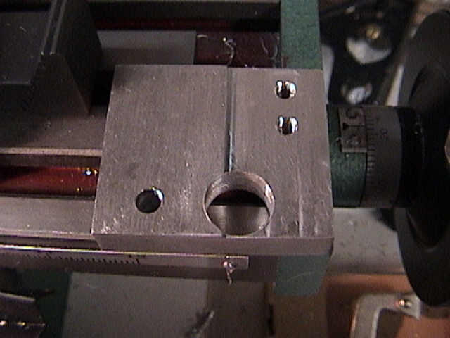
The whole scale can
be mounted with two pieces of aluminum angle. This is about 1 1/2 inch
by 1/8 inch thick aluminum angle, so it's moderately sturdy. There was
nothing where the bolts go through, so I drilled and tapped for two M6-1.0
bolts. Might as well have everything on the mill metric. |
 |
On the bottom, the
bracket is mounted similarly. I wanted the brackets to hold the scale
behind the Z axis feed. Cast iron does well for tapping, and I was
moderately careful to clean up afterwards, although this picture doesn't
show it. |
 |
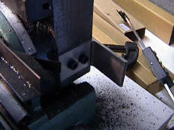
Holding the scale
in place with a clamp allows me to see just what will fit and what will not,
and to check clearances. The brackets are lined with the back of the
column, and the scale has slop in the mounting holes to go left/right. |
 |
Determining the
maximum upwards position of the scale. I want to clear the handles,
and still have the scale up as high as possible. |
 |
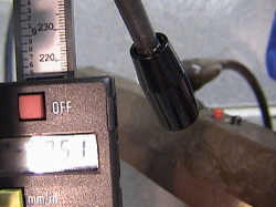
The scale can go
quite low, but there's enough clearance at the bottom so the scale does not
bottom out on the runner. |
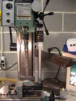 |
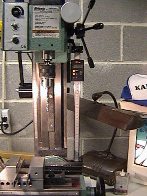
Here's the overall
view. If you think that stuff looks close, you're right. If I'd
been working a bit differently, I'd have put the scale on the side, but
facing to the right. However, without a readout, I can't see what's
going on, so it's better like this. |
 |
Mounting the scale
is relatively easy, you need a bracket and a piece of metal. The
original bracket can't be used, because it goes in the wrong direction.
The mounting point would have to be behind the scale. |
 |
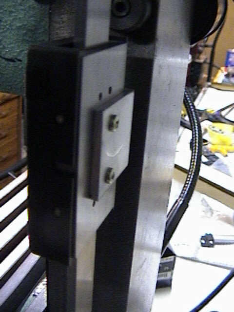
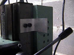
Viewed from the
back, the new mounting bracket is a good fit. |
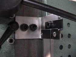 |
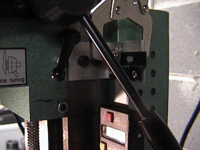
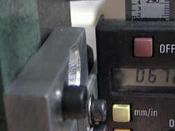
Just to think of
clearances, the gib locking knob is just far enough back that the end of the
handle will just clear the scale. I'd have liked more clearance, but
it does work. I can always reset the handle a bit. As a note,
the screw going through the scale is M5-0.8. |
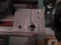 |
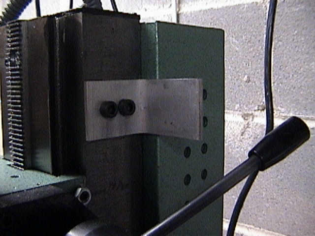
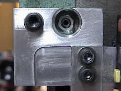
The flat plate of
metal joins the mill head to the bracket. Since the head edge and the
column are just about flush, the plate has to be milled back a bit for
clearance. The plate also covers one of the gib screws, so that has to
be fixed. One screw is sufficient to hold the bracket in place.
It's an M6.0-1.0. |
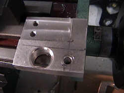 |
The bracket front
has to be milled down because the piece of metal is too thick, and the
bracket needed to be thinned a bit. No big deal, I machined to a
little more than I needed, and allowed the slots in the scale to take up the
adjustment. The bracket that holds the scale bracket is fastened with
M5.0 hardware. Take care that it is not too long, since you can clamp
the head to the column if you're not careful. One M6.0 screw holds the
bracket. |
|
 |
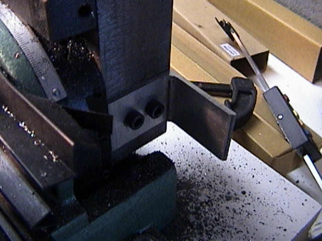
Here's the bracket, side view. The
metal under the screw into the headstock is solid, not hollow here, so I had
to drill deeply and tap for a shorter screw. |
 |
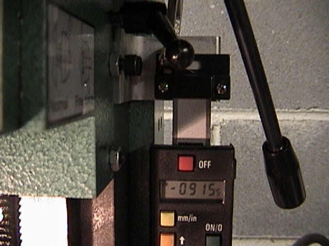
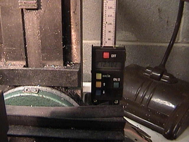
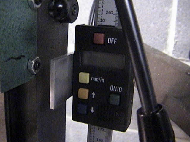
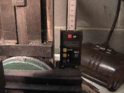
Front view of the Z
axis scale. Finish on all the metal is made with an orbital sander. |
 |
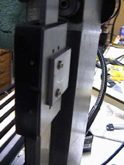
In the very back,
you can see the nut for the torsion spring. There's about 1/16 inch
clearance between the bracket and the end of the spring, but I checked that
to start with. |
 |
Here's the bracket
from the side. I cut the slot too far over, picked the wrong hole to
align with, but no big deal. There's enough clearance to get a socket
wrench to the locking bolt for the gibs. |
 |
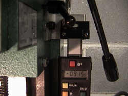
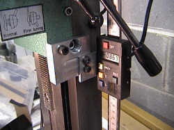
One problem is that
the connector for the readouts is rather close to the handle. If it
becomes a problem, I'll shorten the handle sections |
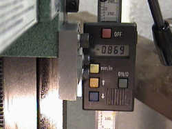
| So here
we are, I've managed to install the Z axis readout. I do find that a
single unified readout would be a really nice idea, but I won't go there
yet. I really need the connectors for the scales, and then I have to
build the display units. I think that I will probably use 3
microprocessors, each with much the same program. I think that they
will probably share a serial line and transmit all the serial data... or
that might possibly be a fourth microprocessor, depends. Naturally, I
have to finish the emulator to see what goes on in the system and get the
program running properly. Nothing, however, keeps me from using it
without an external readout.
I think that if I CNC this mill, I will use these as the
position readouts, and just make a closed loop feedback system. |